Eddy current sensors belong to the category of non-contact displacement sensors. The name-giving principle admits the distance measurement towards conductive objects. As a speciality of this technology - the presence of non-conductive mediums like oil, water or coolant does not affect the measurement. This circumstance predestines the eddy current sensor for applications in the rough industrial environment.
Furthermore eddy current sensors are perfectly suited for the observation of dynamic events. Eddy current sensors of the TX-Series stand out with an excellent dynamic range >100 kSa/s and resolutions in the sub-micron range. With this premise the eddy current sensor is suitable for general motion analysis and in automotive applications.
Besides robustness, high dynamics and high resolution the TX-Series also stands out with a wide temperature range. With a temperature range from -60°C up to 180°C eddy current sensors are the ideal choice for applications in combustion engines.

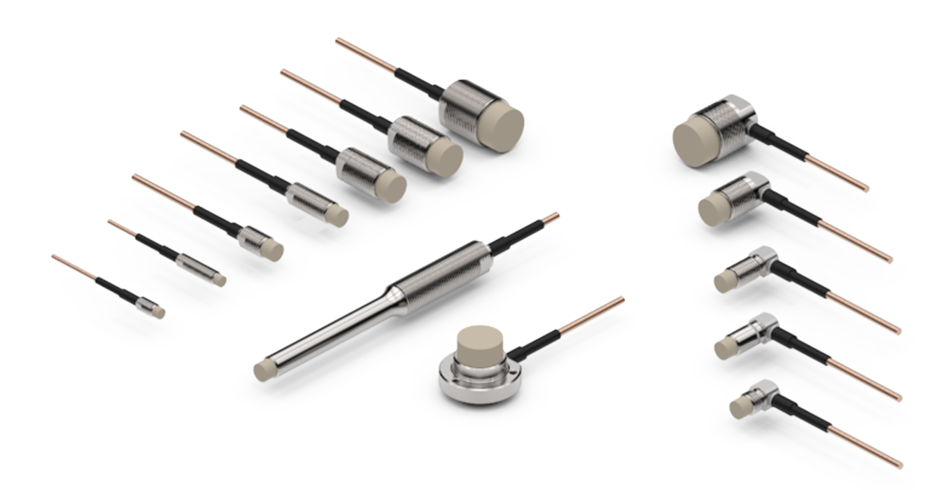 Eddy-current sensor for measuring ranges up to 10 mm, T-series
The sensing element of an eddy current sensor is the coil of an oscillating circuit. The oscillating circuit is made up of the actual probe (inductance) and an interconnect capacitance. The sensing electromagnetic field is emitted from the probe (coil). The electromagnetic field induces eddy currents on the surface of conductive objects (i. e. metallic objects). These eddy currents counteract their cause and attenuate the amplitude of the oscillating circuit. This attenuation effect is inversely proportional to the distance between object and sensor. The TX-System is driving the oscillating circuit and interprets the attenuation as position.
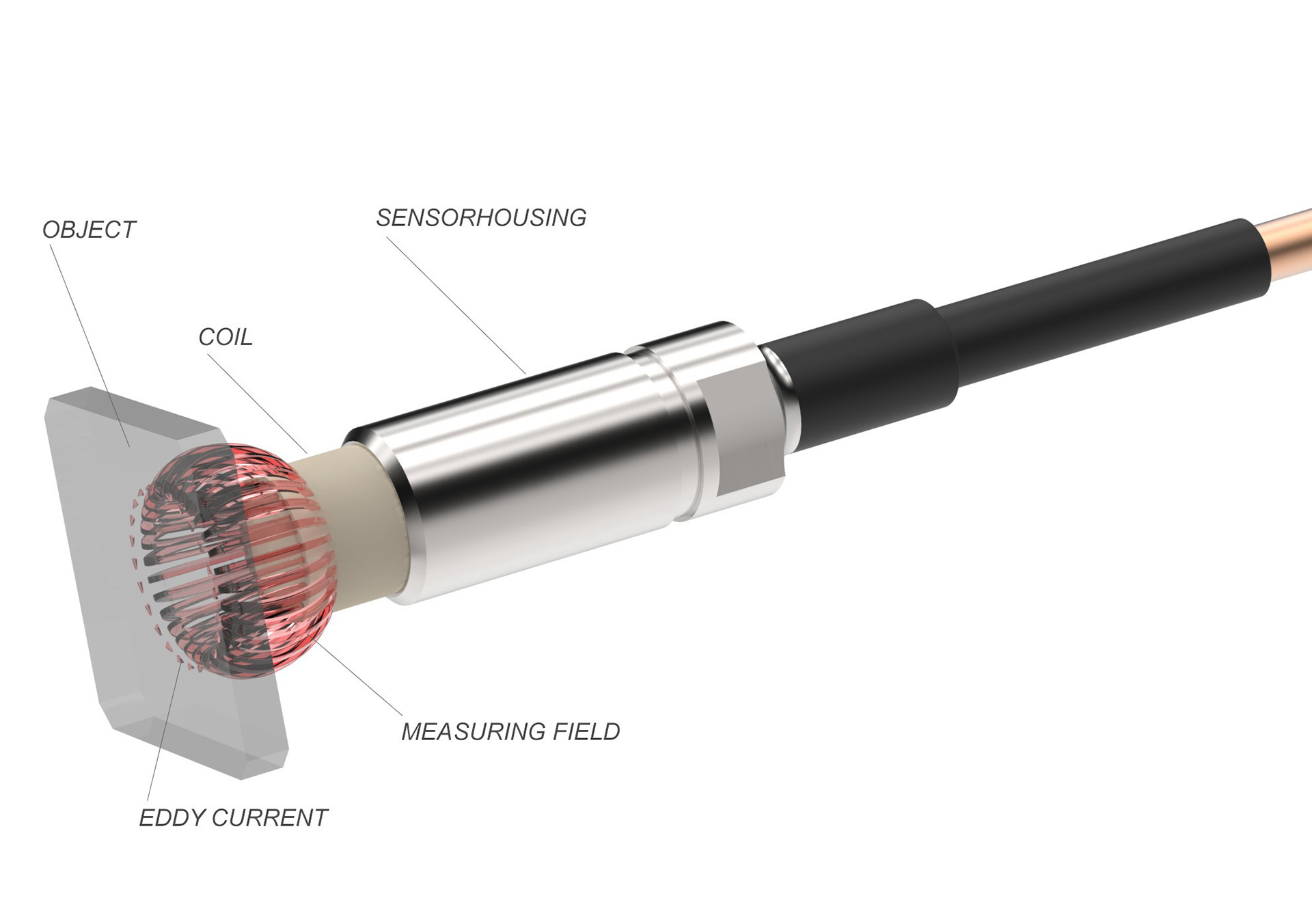 Eddy current principle
The eddy current sensor must resist hardest conditions. Eddy current sensors are utilised at high temperatures and high pressure, within oil or coolant and in strong electromagnetic fields - and various combinations. In particular operation at high temperatures presents enormous challenges to materials and processing technology. As for example - every eddy current sensor has to go through a 12h temperature treatment before the final calibration is carried out. The sensors are specified for operation between -60°C and 180°C. Within this temperature range typical temperature coefficients are ±0.05 % of MR/K. Within the technically relevant range between ambient temperature and 120°C - typical for oil lubricated engine components - the temperature coefficient is at ±0.03 % of MR/K.
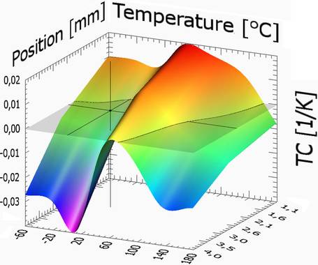 Temperature coefficient as a function of the position and temperature
When it comes to extreme applications like the observation of an operating disc brake we also provide sensors with an integrated water cooling system.
All sensors fulfil the protection class IP68. In applications at high pressure and aggressive mediums we also provide custom-made sensors with ceramic components and further protection features. Modern and highly functional assemblies quite often require compact sensors. Smart solutions are our speciality - we provide custom-made sensors at low quantities and if necessary individual items.
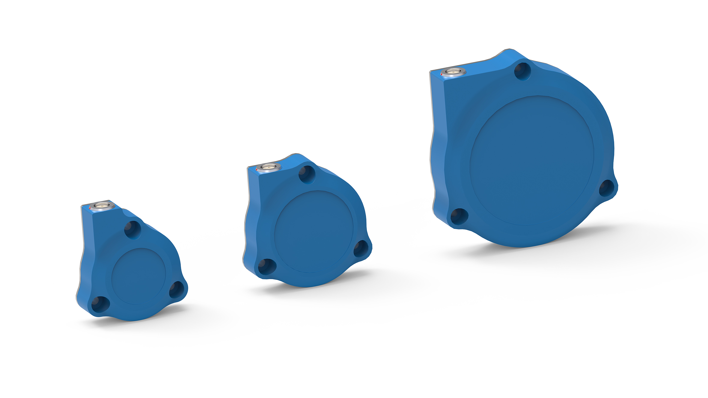
The ultra-compact CM-series from eddylab are eddy current sensors, excellent for use in harsh industrial environments under high pressure and temperature conditions. The ceramic housing can be used as the pressurised component, there is no extra housing needed. All CM sensors are shielded. The combination of shielded coil and ceramic housing guarentees an universal use in limited space of machine parts. Measuring of lubrication gap of crankshafts is a typical application for the CM series.
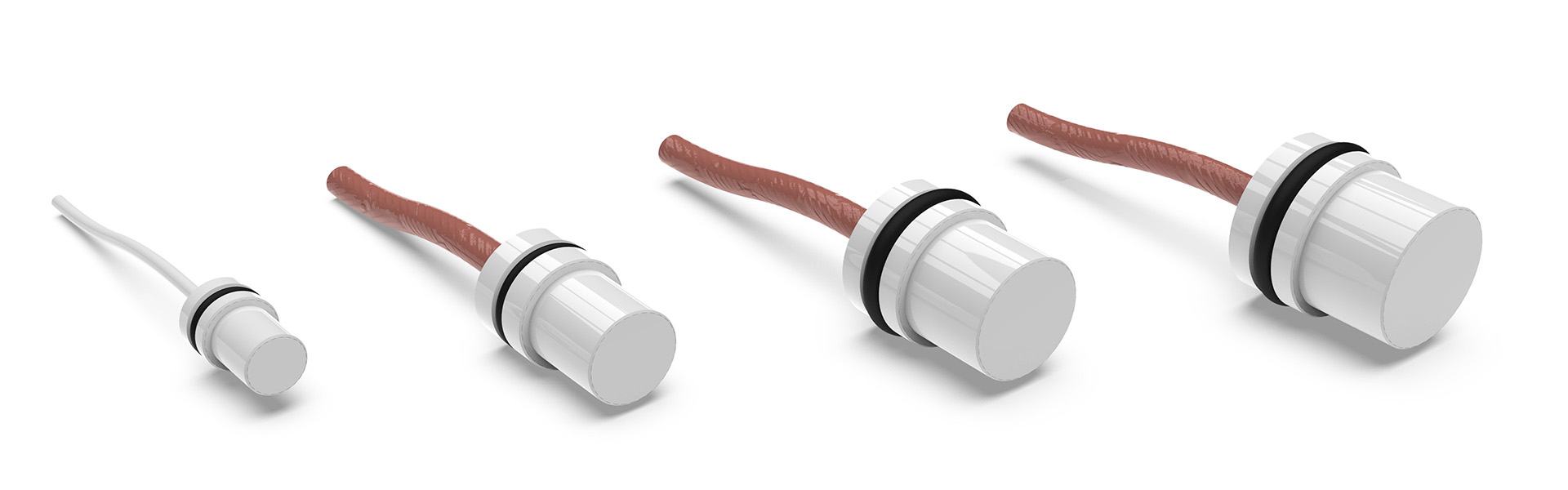 Ultra-compact ceramic sensors, CM-series
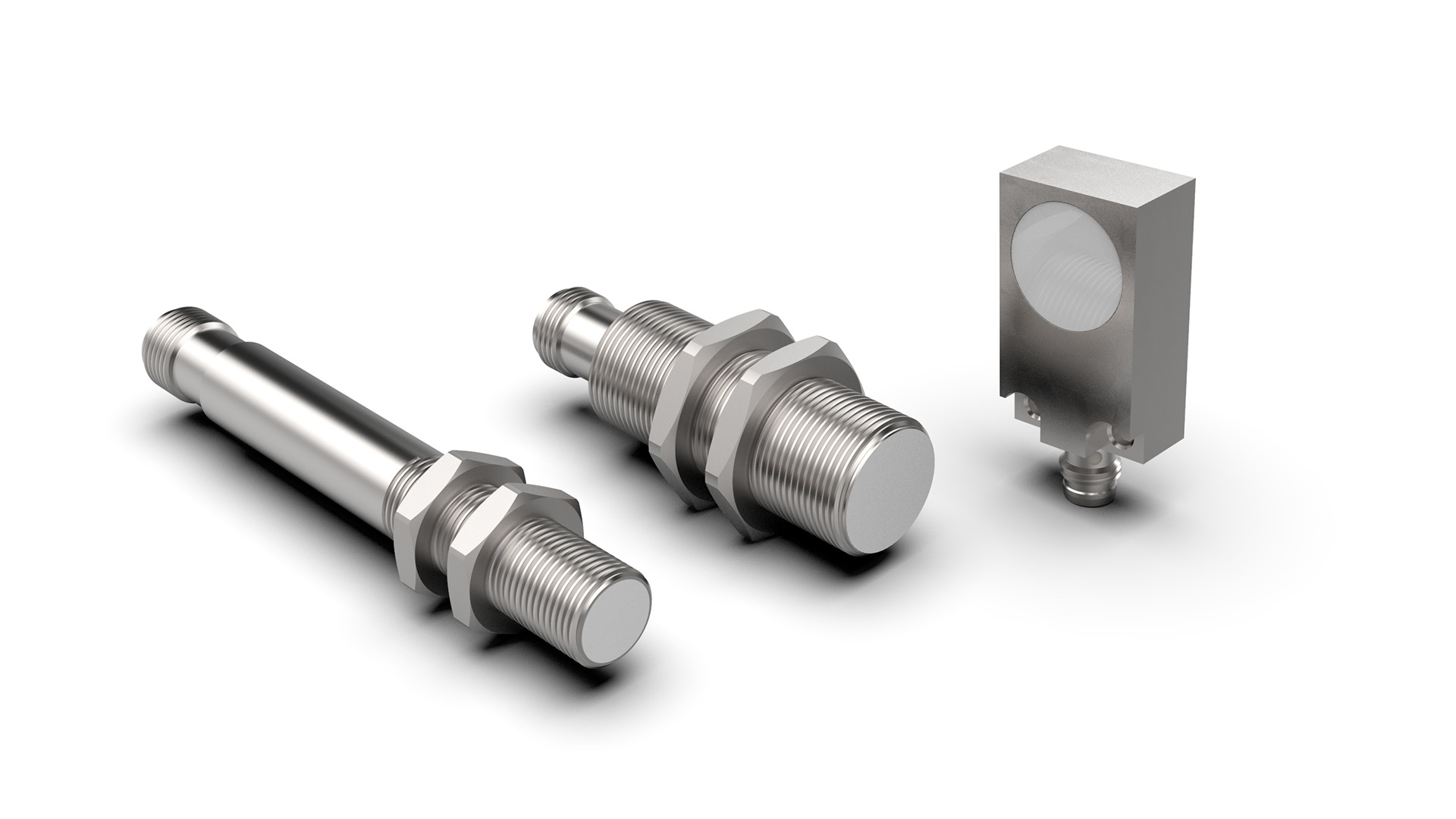
The eddy current sensor series T14/T20/T40 is suitable for measuring ranges up to 45 mm and can easily withstand extreme temperatures in a range of -40...+150 °C. Eddy current sensors of the T14/T20/T40 series are extremely compact, robust and insensitive to external influences such as dirt and dust. This makes them ideal for use in difficult industrial environments or for vibration measurements with larger amplitudes.
 Eddy current sensors for measuring ranges up to 45 mm, T14/T20/T40 series
The CT eddy current sensor series is designed for extreme applications under harsh environmental conditions. All
sensors are shielded and remain unaffected by the surrounding material.
This enables flush installation. At the same time, the shielding focuses the field lines so that the size of the measurement object is minimized.
The CT sensors are suitable for high operating temperatures up to 200°C and are optimized with regard to temperature drift over the entire temperature range.
The sensor head is made of ceramic (zirconium oxide) and the housing is pressure-encapsulated. The CT series is the perfect choice for demanding applications such as pressure chambers or machines where the complete sensor with cable is located within the pressure range. The cable can be protected by two different types of tubing (standard and heavy duty).
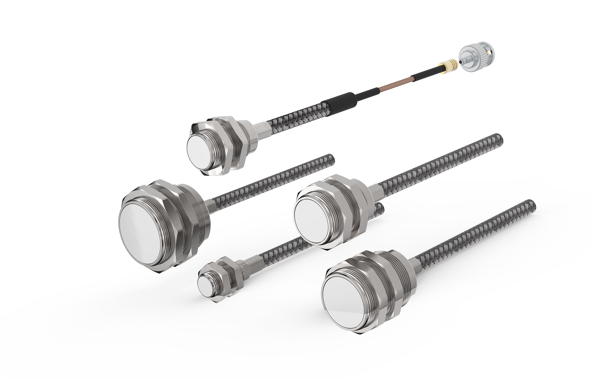 CT Series, pressure-resistant sensors for extremely harsh conditions
The IC eddy current sensor series with newly developed integrated signal processing guarantees highly accurate measurements thanks to linearized characteristic curves. The accuracy has been improved by a factor of up to 20 compared to previous models.
The teach-in function allows the measuring range of the eddy current sensor to be optimally adapted to the respective application. Installation tolerances or material properties of the measurement object can be compensated for directly. Setting individual measuring range limit values offers the user the greatest possible flexibility and simplifies sensor integration. The electronics is built into the sensor, installation and mounting are also extremely simple.
The IC eddy current sensor series is insensitive to extreme temperatures from
-25 to +75 °C and is predestined for demanding environmental conditions in harsh industrial environments. Displacement measurement with eddylab sensors is contactless and wear-free based on the eddy current principle and is characterized by precision and dynamics.
 Cost-effective eddycurrent sensors with integrated electronics
Together with the TX electronics from eddylab GmbH and the eddy current software eddyMOTION, eddy current measurement data can be analysed, visualised and documented. In addition to the configuration of the sensors, eddyMOTION also offers on-site linearisation of eddy current sensors.
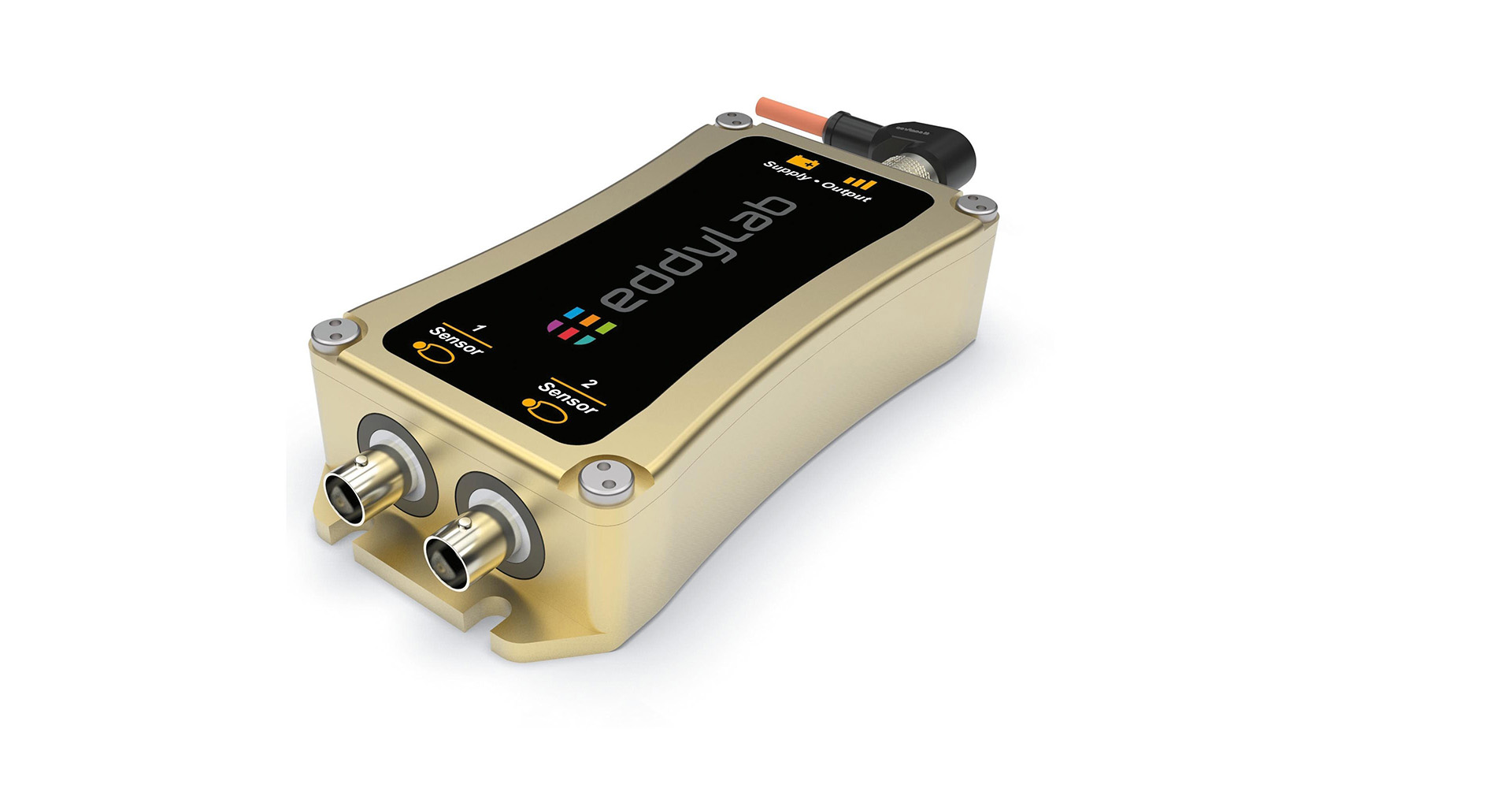
 TX-Driver
The energy saving TX-Driver is the core part within the eddy current measurement. The 16bit-System is driving the oscillating circuit, processes the position and provides five interfaces. The supply voltage is 11..36 VDC or 11..27 VDC in the Ref-Version. The temperature coefficient of the TX-Driver is -0.025 % of MR/K, the maximum operating temperature is 50°C. The power input is 4W. In order to fit the actual measuring task - the edge frequency of a digital low-pass filter can be adjusted. The sampling rate is 70 kSa/s in the two channel version and 124 kSa/s in the single channel version. With 124 kSa/s it is eventually possible to observe motion within the lower ultrasonic range. The maximum sampling rates (70 kSa/s and 124 kSa/s) are available for the analogue interfaces 0..10 V and 4..20 mA.
As additional digital interface we provide the CAN-Bus. This interface is in particular useful for applications with several distributed TX-Drivers - all devices communicate with one cable. Hence - the achievable sampling rate depends on the number of devices on the bus. Using one cable for all devices instead of one analogue input for each sensor enormously reduces costs. This makes the CAN-Bus a cost saving option to analogue interfaces particularly in applications with limited dynamics.
As an option we provide the TX-Driver with reference input. This reference input (A/B increments) can be interfaced to a digital gauge (Magnescale DK-Series) or a rotary encoder. Once interfaced the digital gauge can be used as a reference system. The necessity of a compact and highly accurate reference system is related to the material dependent accuracy behaviour of eddy current sensors. With a digital gauge the end user can either prove the accuracy of an eddy current sensor or linearise the sensor.
It's also possible to connect a rotary encoder instead of a digital gauge. This expansion is in particular useful for the observation of rotating systems. The rotary encoder - coupled to a shaft - returns the angle or the rotational speed of the respective shaft. The TX-Driver synchronises the eddy current signal with the rotary encoder. This function is a premise for the module Waterfall Rpm.
 Waterproof and pressure-tight analog electronics, AX-series
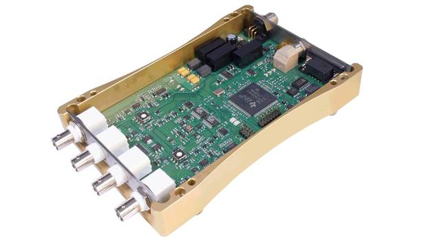
The AX-driver from eddylab is a pressure-tight and waterproof, analog electronics for eddy-current sensors. A customized molding procedure admits subsea operation of the entire system.
The CNC-machined electronic box is sealed with an O-ring. The frontsided connection between eddy-current sensor and housing is achieved with a hermetically sealed LEMO-connection. The M12-connection on the rear side is also IP68 rated and withstands pressures up to 10 bars. The high degree of pressure resistance between the cable and the connector comes with a specialized injection molding process. The injection process crosslinks the cable’s TPE-jacked and the connector to a monolithic unit.

eddyMOTION is an analysis- and configuration tool for windows used in conjunction with the TX-Driver. Communication is based on the USB. The targeted area of application is the visualisation and documentation of mechanical motion and the on-site linearisation of eddy current sensors.
eddyMOTION as analysis tool
eddyMOTION is made up as a universal analysis tool for the USB based data stream from the TX-Driver. The requirements in signal analysis can be of various nature - therefore eddyMOTION is structured in several modules. The different modules can be used to monitor fast and slow motion. The measured data can be displayed in the time- and in the frequency domain. The underlying sampling rates are 22.5 kSa/s in the two channel version and 38 kSa/s in the single channel version.
The oscilloscope is the ideal tool for the analysis of dynamic events. As the name suggests - the module oscilloscope is mostly similar to a classical oscilloscope. Handling this module is fairly easy for everyone with basic experience in oscilloscopes. The functional range of an oscilloscope is ideally suited for the observation of eddy current motion. eddyMOTION replaces the voltage (classical oscilloscope) with the position from the TX-Driver. It is basically possible to visualise periodic and non-periodic motion. In the trigger mode data acquisition is event based. A typical example for this mode is the storage of the signal before and after passing a threshold value in a defined time window. The figure below shows the event based data acquisition of a tuning fork while triggering it. Another useful function is AC-coupling. This feature displays the variation of the position instead of the absolute position (the position value oscillates around zero). This function is in particular useful for the visualisation of vibration with small amplitudes. Measurements on the captured data can be taken. These are the frequency, the amplitude and the maximum and minimum values. Captured data can be exported as picture or text-file.
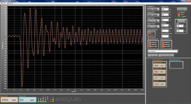 Triggering a tuning fork
The spectrum (FFT) offers a view to all frequency components within the signal provided by the TX-Driver. This enables the visualisation of fundamental and harmonic oscillations. The single channel version provides a frequency range up to 19 kHz. This covers the acoustic range. The figure below is the spectrum of a tuning fork. Besides visualisation - the frequency components are analysed above a defined threshold. The figure clearly shows the fundamental oscillation with 49 µm and a second and third harmonic with 250 nm and 100 nm. Same as with the oscilloscope the spectrum can be exported as picture or text-file.
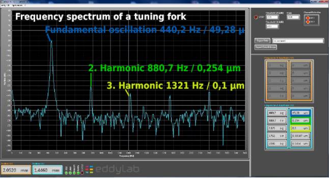 Spectrum of a tuning fork
Waterfall and Waterfall Rpm are three-dimensional FFTs. The waterfall is a classical FFT expanded with a time axis. The 3D-plot provides a new view to your spectrum as it can observed over time. The third axis emphasises small peaks above the noise floor. These small peaks can easily be missed in a 2D-plot in particular when these small peaks emerge and disappear over time. The figure above illustrates this effect clearly. The waterfall shows the spectrum of a tuning fork 28secs after triggering it. The plot obviously shows that the oscillations at 881 Hz and 1320 Hz disappear and re-emerge over time.
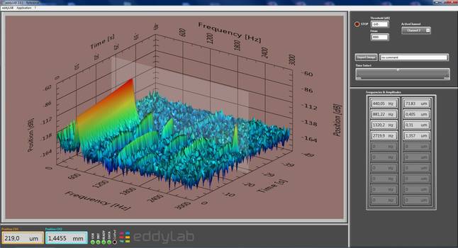 Waterfall of a tuning fork
The rpm-based waterfall is a FFT expanded with the rpm-axis of a rotating shaft. The basic requirement for this function is a rotational incremental encoder mounted on the shaft. The TX-System synchronises the incremental signal with the eddy position. The correlation of rotational speed and FFT results in a characteristic three-dimensional plot. The plot may characterise the state of a rotating system depending on loads, oil-pressure, wear and similar aspects. This admits comparisons of the same system at different times under varying conditions. The figure above is the rpm based waterfall of a shaft with a resonance frequency of 6000 rpm. The amplitude peaks along the ascending and descending path of the rotational speed.
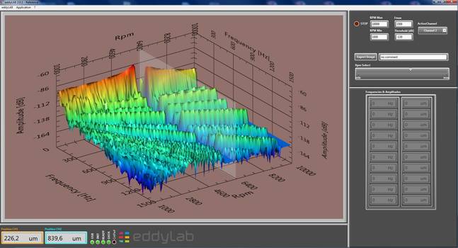 Rpm-based waterfall of an overcritical rotating shaft.
The frequencies and amplitudes in the time- and the rpm-based waterfall can be analysed within the analysis plane. This plane can be moved along the time- and rpm-axis.
eddyMOTION as linearisation utility
The mobile linearisation is one of the key features on the TX-Driver. The necessity of a mobile linearisation has a well known reason. The accuracy of eddy current sensors is a strong function of the material they are looking at. The maximum scaling error under varying target material can be 20% or more. The linearity error can be 7% or more. Another severe error source affecting the accuracy is pre-attenuation. This effect has to be taken in account when the sensor is mounted in narrow gaps and holes. The reason of this error is given with the shape of the sensing electromagnetic field. The basic idea of the sensor is to measure in one dimension with an electromagnetic field. If the shape of the field 'collides' with an object other than the target - the measured result will be incorrect. This effect is called pre-attenuation. Typical 'not relevant' objects are screws and nuts. The error due to pre-attenuation is hard to predict - but in most cases higher than expected. The figure below reflects the typical error behaviour on eddy current systems (red dotted line).
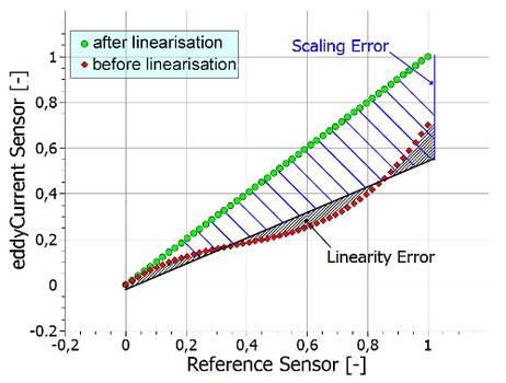 Illustration of typical errors on eddy current systems.
The TX-Driver in conjunction with eddyMOTION resolves these issues with an integrated linearisation procedure. The backbone of the method is an interface to a linear encoder on the TX-Driver. This encoder is used as a reference signal. The reference can be used to either prove the accuracy of the sensor or to linearise the sensor. The linearisation is based on a user-defined number of positions (maximum 50). The TX-Driver can store four user-defined curves. The reference interface also contains a power supply. All in all - the TX-Driver is capable of referencing its own sensors on-site. The profit for the customer is obvious: On the one hand it is possible to use an eddy current sensor for different materials without return. And on the other it is possible to prove the accuracy of the sensor on-site at maximum precision. The reference system (Magnescale DK-Series) we provide has a resolution of 100 nm and an accuracy of 0.5 µm over 10 mm. The clamping diameter is 8 mm. The combination of compactness and precision offers a wide spectrum of application. Our compact linear stage with a total weight of 1.1 kg makes the mobile linearisation an easy task for everyone. The reference system records the distance with a resolution of 100nm. The eddy current sensor and the reference sensor are aligned accurately to each other. Different materials can be exchanged easily in a quick release socket. The result is a on-site calibration with an accuracy in the dimension of our laser-interferometric factory calibration.
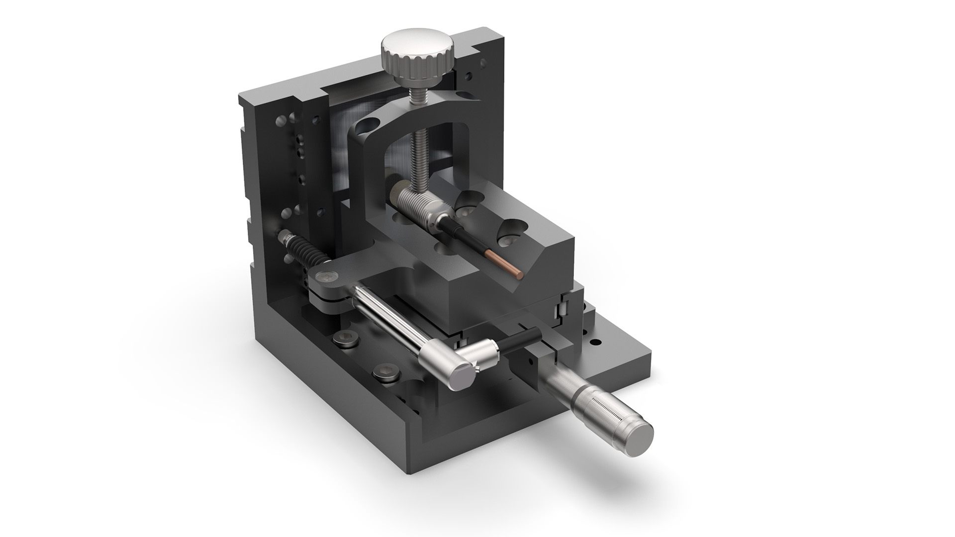 Portable linear stage with a linear
encoder (Magnescale) - eddy current sensor and
a target with the dimensions 50x50 mmt
For further information have a look in our data sheet or the CAN-BUS documentation.